📌 1. If your tensile tester fracture point isn’t centered, your data may be invalid
Many users operating a tensile tester face the same issue: the specimen breaks near the grip area rather than within the gauge length. While this may seem like a minor deviation, most international standards define such a fracture as a test failure—rendering the result unacceptable for product validation, certification, or customer delivery.
This problem is rarely due to material quality or machine precision. In most cases, three critical setup mistakes are to blame. This article breaks down these three details—grip alignment, specimen preparation, and speed setting—to help you regain control over fracture location and data reliability.

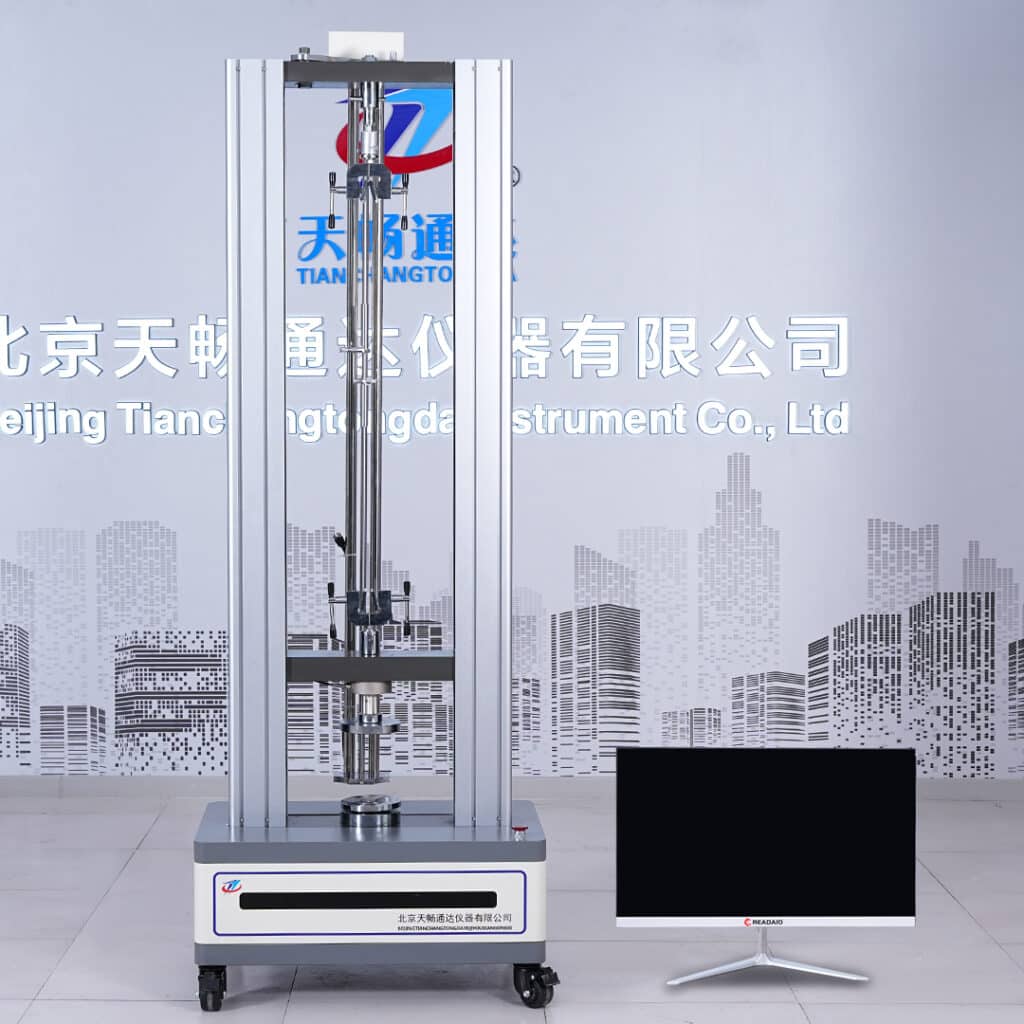
🔧 Tensile Tester
This tensile tester features adjustable test speed, stable gripping force, and support for extensometer alignment to ensure consistent fracture positioning.
🔍 View Tensile Tester Product Details🔧 3. Misaligned grips cause off-center stress and early fracture
If the upper and lower grips of the tensile tester are not aligned on the same axis, the specimen will be pulled unevenly. This leads to localized stress concentration on one side, which often results in fracture near the grip instead of within the gauge length.
Typical symptoms:
- Fracture consistently appears near the same side;
- Sample tilts during initial loading;
- Load-displacement curve shows abnormal spikes or drops.
✅ Solution:
- Use self-centering pneumatic grips or spring-loaded compensation grips;
- Perform zero-load balancing after mounting each specimen to verify symmetry.
📏 4. Poor specimen preparation introduces asymmetrical stress
Improperly prepared specimens—with burrs, rough edges, or uneven shoulders—can create stress risers outside the gauge zone. These imperfections shift the fracture zone toward the gripping ends.
Common errors include:
- Asymmetrical shoulder machining;
- Thickness variation across the width;
- Non-standard, hand-cut specimens.
✅ Recommendations:
- Use CNC cutters or laser dies for consistent shape;
- Ensure smooth shoulder transitions and accurate gauge length alignment;
- Deburr all edges and check flatness before mounting.
⚙️ 5. Incorrect speed setting disrupts natural fracture behavior
Test speed plays a major role in fracture dynamics. If the tensile tester is set to an overly high speed, the material may rupture before undergoing uniform plastic deformation. This abrupt failure often occurs at the grip edge.
Standard speed recommendations:
- ASTM D638 (plastics): 50 mm/min
- JIS K 6251 (rubber): 200–500 mm/min
- ASTM D882 (films): 500 mm/min
✅ Tip: Create speed templates in your testing software by material type to avoid manual errors.
📘 6. What do the standards say about fracture location?
Multiple international standards explicitly define where a fracture must occur for a test to be considered valid:
- ASTM D638: Fracture must occur within the gauge length, not near the grip;
- ISO 527-1: Breaks outside the gauge area are excluded from formal results;
- JIS K 6251: Requires photo evidence and fracture location notes in the test report.
📘 Reference links:
ASTM D638 | ISO 527-1
✅ Best practice: Use a non-contact extensometer and record every fracture with a timestamped photo for traceability.
✅ 7. Final Thoughts: Accuracy is not just load—it’s location
A fracture outside the gauge zone is not a small issue. It defines whether the test data from your tensile tester is accepted or rejected. Without proper alignment, specimen preparation, and speed control, repeatability and compliance become impossible.
We recommend establishing an internal SOP that includes:
- Grip alignment verification;
- Specimen quality inspection;
- Standardized test templates by material.
Also, maintain a log of fracture photos and speed settings for audit and customer validation.
Need help resolving fracture inconsistencies? Contact us for technical consultation and setup optimization.